Access Control
IDE-DC100
Single-door access controller — Wi-Fi
The IDE-DC100 is a compact, single-door controller for installations where running a cable to a central controller is impractical. Mount it near the door, connect it to a local 12–24 V AC or DC supply and the reader, and bring it online over Wi-Fi. Its bridge-rectified input accepts either wiring polarity.
- Door
- 1 door
- 1 × Form C relay, 30 V DC / 5 A
- Reader
- 1 × Wiegand
- Detects card format
- Inputs / outputs
- 3 · 3
- Optically isolated inputs
- Network
- Wi-Fi
- 2.4 GHz · Bluetooth LE
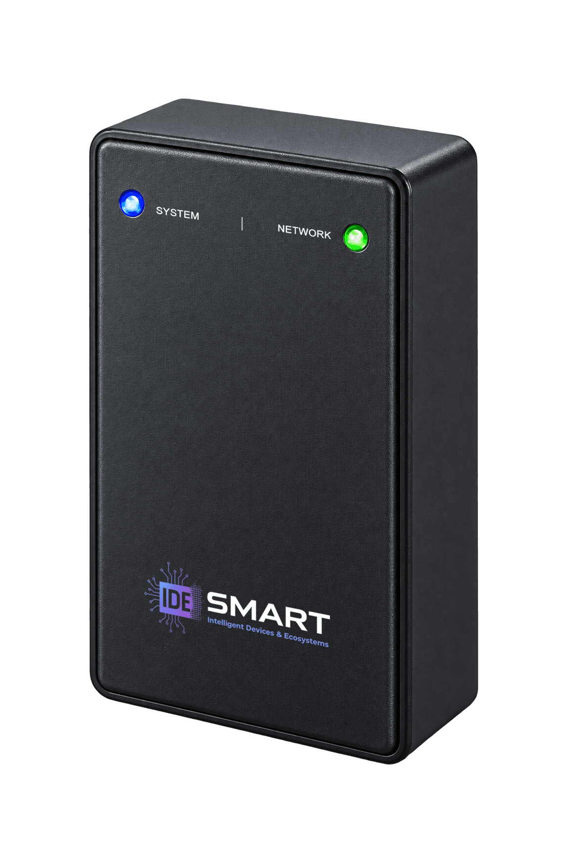
IDE-DC100ABS, UL94-HB · 92 × 58 × 27 mm
- 2.4 GHz Wi-Fi, internal antenna
- 12–24 V AC/DC, either polarity
In the field and in operation
Key features
The controller makes the decision, so a network or server outage never stops the door.
Access control continues during network outages
Credentials, permissions and schedules are stored on the controller. A Wi-Fi or server outage does not interrupt local access decisions. The controller buffers up to 200,000 access events while offline and sends them when connectivity returns.
200,000 offline records
Designed for single-door retrofits
The controller is installed near the door and needs only local power and reader wiring. Wi-Fi eliminates the network cable run to a central controller.
No cable run to a central controller
Flexible AC/DC power input
The bridge-rectified input accepts 12–24 V AC or DC, regardless of the polarity of the two input wires. It can use a suitable existing door or lock supply.
12–24 V AC / DC
Automatic card-format recognition
The controller recognises supported 26-, 34-, 35- and 37-bit formats, including HID H10306, H10304, Corp 1000, Honeywell/Northern and iCLASS. Raw-value fallbacks are available for HID Prox, Mifare CSN and iCLASS UID. Present a card to a reader on the site to enrol it through the software.
26–37-bit Wiegand
Direct system integration
The controller provides both an HTTP server and an HTTP client. It can post live access events and buffered events to an external system, or an external server can retrieve them using a fetch-and-acknowledge exchange. The published protocol includes exact sample messages and a runnable reference receiver.
HTTP push and pull
Built-in mobile credentials
Bluetooth Low Energy (BLE) supports phone-based access alongside the card reader, without an additional door-mounted module.
Bluetooth LE
Remote firmware updates with automatic recovery
The management software can deploy firmware across a fleet. Updates can be applied automatically, with a configurable check interval and time of day, so that they are installed outside working hours. If the updated firmware fails to start, the controller automatically reverts to the previous working version.
Scheduled update window
Alarm functions are built into the controller
A motion sensor connects to a controller input and a siren is driven from a controller output. Alarm partitions are armed and disarmed by presenting a card at the door reader. There is no separate alarm panel to buy and no integration between two systems to build.
Armed and disarmed by card
“Why did the door not open?” is answered in the log
When a request is refused, the reason is recorded with it: was the card unrecognised, does the user lack permission, was the attempt outside the permitted hours? Complaints and incidents are investigated directly from these records.
11 distinct refusal reasons
Every site is managed from one place
The controller opens the secure connection to the management server itself. No fixed public IP, port forwarding or VPN setup is required; controllers in different buildings and cities are managed from the same screen.
No open ports or VPN
Protected connection interfaces
The three inputs provide 5 kVrms optical isolation. Transient suppression is fitted to the power input, RS-485 lines and field connections.
5 kVrms isolated inputs
Technical detail
Specifications
- 40,000
- Credentials (cards, PINs and mobile)
- 5,000
- Permission rules
- 5,000
- Schedules
- 60,000
- Usage-limited credentials
- 200,000
- Offline access-event capacity
A card, PIN and mobile credential registered to one person count as three credentials. They share one identity, permission set and anti-passback position.
The controller's behaviour when the log is full can be selected. Preserving the existing records means the oldest entries are never overwritten and new requests are refused; keeping access available means new events overwrite the oldest records. The first option gives priority to the existing audit history, the second to entries continuing and current events being recorded.
The maximum number of permissions per person is configurable. Higher limits reduce credential capacity as shown below:
- Permissions per person
- Credentials
- 16
- 40,000
- 32
- 40,000
- 48
- 29,000
- 64
- 23,000
- 128
- 12,500
- 255
- 6,500
Access decisions are made on the controller without a server round trip.
Access control functions
Multi-credential authorisation
Credentials from 2–8 different authorised people are required within a configurable 1-second to 1-hour window. Re-presenting the same credential does not count.
Anti-passback
Zone status is replicated directly between controllers without a server connection, allowing site-wide global anti-passback. Configurable per door. Hard and soft anti-passback are both supported.
Door interlock (mantrap)
Not available on this single-door model. See IDE-DC300.
Fire and emergency release
A configured input holds the door released for egress until the condition clears.
Alarm partitions
Scenarios are grouped into partitions. A partition is armed or disarmed with an authorised credential; motion in a disarmed partition produces no action.
Exit button
Any input can be configured as a direct exit-button input.
Door contact
Accepts a turnstile-rotation signal, and detects forced opening and doors held open, with a configurable timeout. If no door contact is fitted, its input remains available for another function.
Time schedules
Schedules, holidays and date ranges are evaluated on the controller.
Usage-limited credentials
A credential is valid for a fixed number of entries, counted per door.
Scenario engine
Rules stored on the controller, triggered at set times or by input state, door events and access events. A triggered scenario can run a relay for a set period, sound the buzzer, drive a relay on another controller, or arm and disarm another scenario.
Detailed access records
When access is refused the reason is recorded: unrecognised card, missing permission, use outside the schedule, exhausted usage allowance, anti-passback rule, inactive or expired record, facility-code mismatch, offline state, door interlock and authentication failure. Forced opening, doors held open and the return to normal are also recorded.
Facility-code check
An accepted facility code can be set per reader. A card whose code does not match is refused, and the reason is recorded as a facility-code mismatch.
Reader feedback
Separate LED and buzzer patterns can be defined per reader for accepted and refused attempts.
Card number format
The facility code and card number can be read as separate fields, or as the long number printed on the card.
Before clock synchronisation
Configurable behaviour before the clock is synchronised.
Offline behaviour
Configurable behaviour when the server is unreachable.
Per-door settings
Settings include unlock pulse duration; relay mode (pulse, toggle or latch); default and power-restore states; early relock on door opening; an option to count access only when the door opens; door-open timeout; anti-passback mode and zone; and usage counting.
Doors, readers and I/O
- Doors
- 1
- Card readers
- 1 × Wiegand
- Relay outputs
- 1 × Form C (NC / COM / NO), dry (voltage-free) contact
- Max. switching voltage
- 30 V DC
- Max. switching current
- 5 A
- Inputs
- 3 × optically isolated (5 kVrms), for dry contacts; configurable debounce
- Reader outputs
- 3 outputs for reader LED and buzzer control
- On-board buzzer
- Yes
- Status indication
- 2 × addressable RGB LEDs
- RTC
- Battery-backed during power loss; synchronised by NTP
The relay contacts include transient suppression and are intended for low-voltage lock loads. Mains switching is not supported.
Connection interfaces
Pre-fitted cable leads eliminate the need to assemble connectors on site.
| Loom | Pitch | Conductors |
|---|---|---|
| Reader and bus | 1.25 mm | Wiegand D0, D1 · RS-485 A, B · IN+, IN− |
| Inputs and outputs | 1.25 mm | OUT1, OUT2, OUT3 · IN1, IN2, IN3 |
| Relay | 2.5 mm | NC, COM, NO |
Wire colour codes
Reader and bus
1.25 mm- 1BlackGND
- 2Red12–24 V IN
- 3WhiteWIEGAND D1
- 4Dark greenWIEGAND D0
- 5Orange-whiteRS-485 B
- 6OrangeRS-485 A
Inputs and outputs
1.25 mm- 1Light greenOUTPUT 3
- 2Green-whiteOUTPUT 2
- 3BlueOUTPUT 1
- 4Blue-whiteINPUT 1
- 5BrownINPUT 2
- 6Brown-whiteINPUT 3
Relay
2.5 mm- 1BrownRELAY NO
- 2BlueRELAY NC
- 3GrayRELAY COM
Cable and distance
| Connection | Cable | Maximum run |
|---|---|---|
| Wiegand data | Shielded AWG22 twisted pair | 150 m |
| RS-485 | Shielded AWG24 or heavier twisted pair; 120 Ω termination at both ends | 1,200 m at the default 9,600 baud; approximately 200 m at 500 kbps |
| Reader power | Distance depends on supply voltage drop; see below | — |
Reader power. The reader draws from the controller supply. The maximum cable length is limited by conductor resistance. For a 12 V supply and a maximum 2 V voltage drop:
| Reader current | AWG22 | AWG20 | AWG18 |
|---|---|---|---|
| 100 mA | 190 m | 300 m | 475 m |
| 150 mA | 125 m | 200 m | 315 m |
| 250 mA | 75 m | 120 m | 190 m |
For long cable runs, check both the data limit and the reader power limit. Use the shorter distance. If the run exceeds the fitted lead length, select the extension cable gauge using the table above.
Communications
- Network
- Wi-Fi 2.4 GHz, on-module PCB antenna
- Bluetooth
- Bluetooth 5 (LE) — mobile credential open
- Data at rest
- Encrypted on the controller
Power
- Input
- 12–24 V AC or 12–24 V DC
- Polarity
- Terminals are marked + and −, but the input is bridge-rectified: reversing them causes neither damage nor a fault
- Protection
- Overvoltage and surge protection
- Controller consumption
- 0.7 W typical, 1.7 W maximum — approximately 60 mA and 140 mA at 12 V
- Reader supply
- No reader output; wire the reader in parallel to the controller's supply
- Recommended supply
- 12 V / 1 A minimum
- Backup battery
- CR1220 coin cell; backs up the real-time clock (RTC) only; does not power the controller.
Size the supply for the controller (up to 140 mA at 12 V) plus the reader's own consumption.
The relay contacts are volt-free. The lock is powered from its own supply and the contact only switches it, so lock current is not part of these figures and must be provided separately.
Integration and interfaces
On-board HTTP server
Accepts direct HTTP commands to release a door, read status, and read or change settings.
HTTP client — push
Posts live and buffered access events to an external server, along with heartbeats and input telemetry.
HTTP server — pull
Allows an external server to retrieve and acknowledge events in separate steps.
Management protocol
MQTT over TLS. The controller opens the connection; no open port, port forwarding or VPN is required.
Serial bus
RS-485, half-duplex; up to 500 kbps and 256 nodes; ±18 kV IEC ESD.
Also available
TCP and UDP
Discovery
mDNS / DNS-SD
Device health
Uptime, restart reason, processor temperature and memory status are reported.
Network rollback
If an incorrect static IP is applied the controller does not become unreachable; it reverts to DHCP.
Documentation
Published protocol specification, exact message samples and a runnable reference receiver.
Mechanical and environmental specifications
- Enclosure
- ABS, UL94-HB
- Dimensions
- 92 × 58 × 27 mm
- Mounting
- Surface-mounted, indoors
- Operating temperature
- 0 to +50 °C
- Humidity
- 10–90% RH, non-condensing
- Ingress protection
- Indoor use
Ordering
- IDE-DC100
- Single-door Wi-Fi access controller
Warranty
The product is warranted against defects in materials and workmanship for two years from the date of delivery.
The following are excluded from this warranty:
- The RTC backup battery
- Damage caused by surges, lightning, overvoltage or a supply outside the specified input range
How it connects
Decided at the door, recorded centrally
The controller opens the secure connection to the management server itself. No open port, port forwarding or VPN is required.
Reader and door
A card, PIN or phone is read at the door reader or over Bluetooth LE.
The controller decides
Permissions, schedules and anti-passback are evaluated on the controller, and the lock relay is driven.
Wi-Fi
Events travel to the management server as MQTT over TLS, and wait on the controller while the link is down.
Management server
Records are collected centrally and can be passed to other systems over MQTT/HTTP.
Not sure which controller fits?
Tell us the door count, the reader type and the network you have, and we will size it with you.